19 Zoll Raspberry Pi 2/3/4 Rack
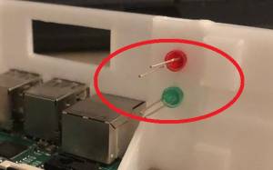
In dem Raspberry Pi Rack lassen sich bequem 4 Pi's unterbringen. Zudem erhalten die Pi's eine Aktivitäts- und beim Pi 2-3 auch eine Heartbeat-LED.
Weiterhin kann der Pi mittels Taster herunter und wieder hochgefahren werden und im Display werden die wichtigsten Informationen angezeigt.
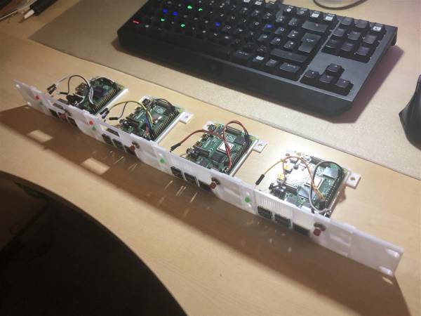
In der kompletten Lieferung sind folgende Komponenten enthalten. Die Blenden sind plugable und können durch Pi 2/3 oder Pi 4 Blenden aneinander gesteckt werden.
Die Reihenfole ist egal. Bei Verwendung von 4 Pi-Blenden und zwei Endstücken kommt man immer auf das 19-Zoll Maß von 48,26cm.
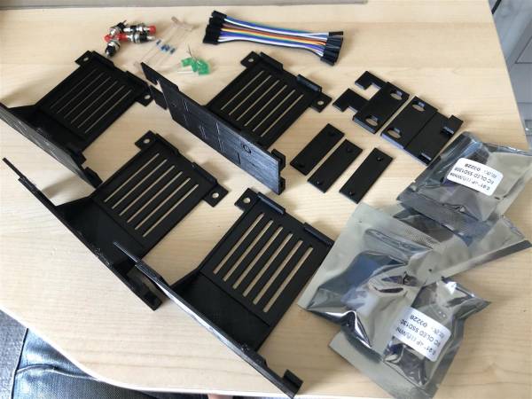
Lieferumfang (je nach Bestellung):
- 4x Blende Pi2/3 oder Pi4
- 2x Endstücke (links/rechts)
- 3x Verbinder
- 4x LED grün
- 4x LED rot (nur Pi2/3)
- 4x Widerstand 680 Ohm (beim Pi2/3 sind es 8 Widerstände)
- 4x Taster
- 4x OLED-Display
- 4x Display-Halterung
- Dupont-Kabel
Stützkontruktion und Transportsicherungen entfernen
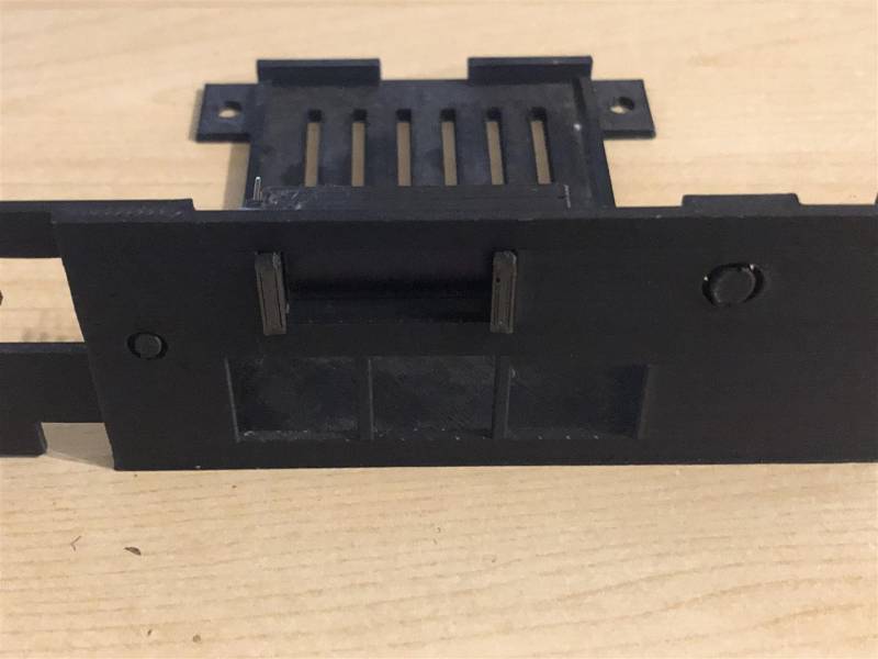
Bitte vorsichtig die markierten Stellen mit einer kleinen Zange herausbrechen. Achtung: Bei zuviel Gewalt, könnten die Haken abbrechen.
Auch zwischen den Haken (Rückseite) muss die Stützkonstruktion vorsichtig mit einer kleinen Zange entfernt werden, da sich sonst die Module nicht einhaken können.
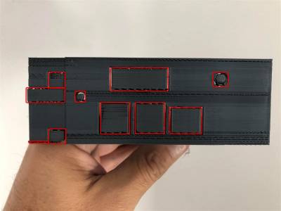
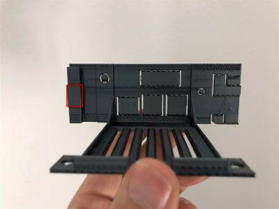
Beim Zusammenstecken ist etwas Vorsicht geboten. Die Blenden lassen sich etwas schwer verbinden aber dass muss so sein, damit sie einen guten Halt haben.
Es kann auch ein Gummihammer verwendet werden um durch leichtes Klopfen die Bauteile zu verankern.
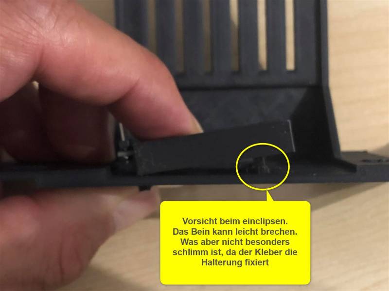
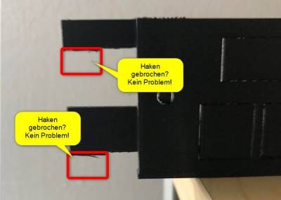
![]() Falls beim Zusammenstecken einer der Verankerungs-Haken abbrechen sollte, ist das nicht schlimm, denn ein Haken alleine bzw. sogar nur der obere Teil des Hakens hält die Konstruktion.
Falls beim Zusammenstecken einer der Verankerungs-Haken abbrechen sollte, ist das nicht schlimm, denn ein Haken alleine bzw. sogar nur der obere Teil des Hakens hält die Konstruktion.
Zusätzlich kann man mit einem Tropfen Kunststoffkleber die Blenden miteinander verkleben. Dann lösen diese sich nie wieder. Das schützt auch vor späterem Rausrutschen oder Abbrechen beim Ein- und Ausbau.
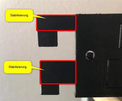
Folgende Teile sind für die Stabilisierung ausreichend:
Falls diese beiden Teile brechen, hat dies sogut wie keinen Einfluß auf die Stabilität:
Die kleinen „Verbinder“ verbinden die Blenden an der Hinterseite und dienen zur Stabilisierung. Diese werden mit etwas Kunststoff- oder Sekundenkleber fixiert.
Somit biegt sich das 19 Zoll Rack nicht durch und hat einen besseren Halt.
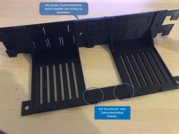
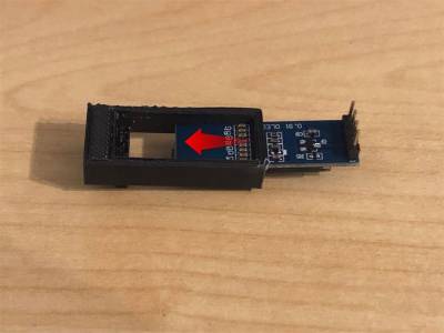
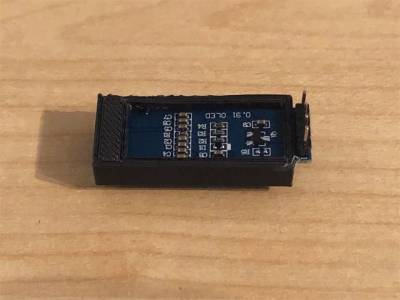
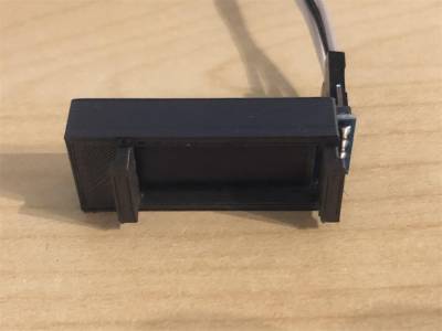
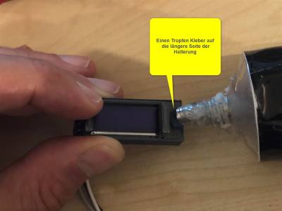
Display Halterung
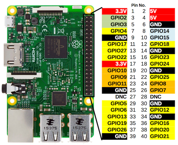
GPIO Pinleiste
An die Pinleiste werden die LED's, der Taster und das Display mittels der mitgelieferten DUPONT-Kabel angesteckt.
LED
Die LED's werden wie folgt angeschlossen.
![]() Beim Pi4 kann nur Grün angeschlossen werden.
Beim Pi4 kann nur Grün angeschlossen werden.
Der Plus-Pol (das längere Bein) der LED's wird an die in der Tabelle aufgeführten Pins (37,38) angesteckt.
Der Minus-Pol (das kürzere Bein) der LED's wird mit einem 680 Ohm Widerstand versehen und gemeinsam mit der anderen LED und dessen Widerstand verlötet und anschließend an GND (Pin 39) angesteckt.
Detaillierte Beschreibung: https://indibit.de/raspberry-pi-externe-status-leds-ueber-gpio-pwr_led-act_led/
| LED | GPIO |
|---|---|
| Rot+ | Pin 37 |
| Rot- | Pin 39 |
| Grün+ | Pin 38 |
| Grün- | Pin 39 |
Taster
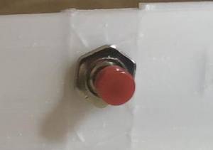
Ein 20cm langes DUPONT-Kabel in der Mitte auseinander schneiden. Ein Kabel wird also somit für einen Taster verwendet.
Dieses wird an die Taster-Kontakte angelötet. Die Stecker werden ganz einfach an Pin 29 und an den gegenüber liegenden Pin 30 (GND) angesteckt.
Detaillierte Beschreibung: https://blog.gc2.at/post/pi-herunterfahren/
| TASTER | GPIO |
|---|---|
| Pin 1 | Pin 5 |
| Pin 2 | Pin 6 |
Code für LED und Taster
Folgende Code-Zeilen sind in die Datei /boot/config.txt einzutragen.
Raspberry Pi 2/3
# Status-LEDs an GPIO weiterleiten
dtoverlay=act-led,gpio=20
dtparam=pwr_led_gpio=26,pwr_led_trigger=heartbeat

# Taster
dtoverlay=gpio-shutdown,gpio_pin=5,active_low=1,gpio_pull=up
Raspberry 3B+ (Power LED)
Den Minus-Pol mit dem Widerstand an GND (Pin 6) anschließen und das zweite Bein an GPIO14 (Pin 8)
enable_uart=1
Raspberry Pi 4
# Status-LEDs an GPIO weiterleiten
dtoverlay=pi3-act-led,gpio=20

# Taster
dtoverlay=gpio-shutdown,gpio_pin=5,active_low=1,gpio_pull=up
OLED 128x32
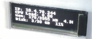
Das Display wird an folgende GPIO Pins angeschlossen und hinter der Blende mit der Display-Halterung (falls mitbestellt) oder mit Heißkleber oder einem Tape (Panzertape oder Gaffaband) fixiert.
| Display | GPIO |
|---|---|
| VCC | Pin 1 |
| SDA | Pin 3 |
| SCK | Pin 5 |
| GND | Pin 6 |
Folgende Installationsabläufe sind durchzuführen:
sudo apt-get install python3-pip
sudo pip3 install adafruit-circuitpython-ssd1306
sudo apt-get install python3-pil
sudo apt-get install -y python-smbus
sudo apt-get install -y i2c-tools
sudo raspi-config
Jetzt startet die Raspberry-Konfigurations. Dort I2c und SPI aktivieren:
1. Interfacing Options > I2C > Enable (Ja)
2. Interfacing Options > SPI > Enable (Ja)
System booten:
sudo reboot
Das OLED detektieren:
sudo i2cdetect -y 1

     0  1  2  3  4  5  6  7  8  9  a  b  c  d  e  f
00:          -- -- -- -- -- -- -- -- -- -- -- -- --
10: -- -- -- -- -- -- -- -- -- -- -- -- -- -- -- --
20: -- -- -- -- -- -- -- -- -- -- -- -- -- -- -- --
30: -- -- -- -- -- -- -- -- -- -- -- -- 3c -- -- --
40: -- -- -- -- -- -- -- -- -- -- -- -- -- -- -- --
50: -- -- -- -- -- -- -- -- -- -- -- -- -- -- -- --
60: -- -- -- -- -- -- -- -- -- -- -- -- -- -- -- --
70: -- -- -- -- -- -- -- --
Script anlegen:
sudo vi /home/pi/stats.py
Inhalt:
# Copyright (c) 2017 Adafruit Industries
# Author: Tony DiCola & James DeVito
#
# Permission is hereby granted, free of charge, to any person obtaining a copy
# of this software and associated documentation files (the "Software"), to deal
# in the Software without restriction, including without limitation the rights
# to use, copy, modify, merge, publish, distribute, sublicense, and/or sell
# copies of the Software, and to permit persons to whom the Software is
# furnished to do so, subject to the following conditions:
#
# The above copyright notice and this permission notice shall be included in
# all copies or substantial portions of the Software.
#
# THE SOFTWARE IS PROVIDED "AS IS", WITHOUT WARRANTY OF ANY KIND, EXPRESS OR
# IMPLIED, INCLUDING BUT NOT LIMITED TO THE WARRANTIES OF MERCHANTABILITY,
# FITNESS FOR A PARTICULAR PURPOSE AND NONINFRINGEMENT. IN NO EVENT SHALL THE
# AUTHORS OR COPYRIGHT HOLDERS BE LIABLE FOR ANY CLAIM, DAMAGES OR OTHER
# LIABILITY, WHETHER IN AN ACTION OF CONTRACT, TORT OR OTHERWISE, ARISING FROM,
# OUT OF OR IN CONNECTION WITH THE SOFTWARE OR THE USE OR OTHER DEALINGS IN
# THE SOFTWARE.


# This example is for use on (Linux) computers that are using CPython with
# Adafruit Blinka to support CircuitPython libraries. CircuitPython does
# not support PIL/pillow (python imaging library)!

import time
import subprocess

from board import SCL, SDA
import busio
from PIL import Image, ImageDraw, ImageFont
import adafruit_ssd1306


# Create the I2C interface.
i2c = busio.I2C(SCL, SDA)

# Create the SSD1306 OLED class.
# The first two parameters are the pixel width and pixel height.  Change these
# to the right size for your display!
disp = adafruit_ssd1306.SSD1306_I2C(128, 32, i2c)

# Clear display.
disp.fill(0)
disp.show()

# Create blank image for drawing.
# Make sure to create image with mode '1' for 1-bit color.
width = disp.width
height = disp.height
image = Image.new("1", (width, height))

# Get drawing object to draw on image.
draw = ImageDraw.Draw(image)

# Draw a black filled box to clear the image.
draw.rectangle((0, 0, width, height), outline=0, fill=0)

# Draw some shapes.
# First define some constants to allow easy resizing of shapes.
padding = -2
top = padding
bottom = height - padding
# Move left to right keeping track of the current x position for drawing shapes.
x = 0


# Load default font.
font = ImageFont.load_default()

# Alternatively load a TTF font.  Make sure the .ttf font file is in the
# same directory as the python script!
# Some other nice fonts to try: http://www.dafont.com/bitmap.php
# font = ImageFont.truetype('/usr/share/fonts/truetype/dejavu/DejaVuSans.ttf', 9)

while True:

    # Draw a black filled box to clear the image.
    draw.rectangle((0, 0, width, height), outline=0, fill=0)

    # Shell scripts for system monitoring from here:
    # https://unix.stackexchange.com/questions/119126/command-to-display-memory-usage-disk-usage-and-cpu-load
    cmd = "hostname -I | cut -d' ' -f1"
    IP = subprocess.check_output(cmd, shell=True).decode("utf-8")
    cmd = "top -bn1 | grep load | awk '{printf \"CPU Load: %.2f\", $(NF-2)}'"
    CPU = subprocess.check_output(cmd, shell=True).decode("utf-8")
    cmd = "free -m | awk 'NR==2{printf \"Mem: %s/%s MB  %.2f%%\", $3,$2,$3*100/$2 }'"
    MemUsage = subprocess.check_output(cmd, shell=True).decode("utf-8")
    cmd = 'df -h | awk \'$NF=="/"{printf "Disk: %d/%d GB  %s", $3,$2,$5}\''
    Disk = subprocess.check_output(cmd, shell=True).decode("utf-8")

    # Write four lines of text.

    draw.text((x, top + 0), "IP: " + IP, font=font, fill=255)
    draw.text((x, top + 8), CPU, font=font, fill=255)
    draw.text((x, top + 16), MemUsage, font=font, fill=255)
    draw.text((x, top + 25), Disk, font=font, fill=255)

    # Display image.
    disp.image(image)
    disp.show()
    time.sleep(0.1)
In Autostart einbauen:
sudo vi /etc/rc.local
… und folgende Zeile einbauen:
...
...
sudo python3 /home/pi/stats.py &
exit 0
